
Graphics Tech
Image quality for real-world simulations depends on the techniques used to render images. Here are some of the methods used.

Page Contents
VR Headsets
Human Eye Resolution in Pixels
Each human eye sees about 130 degrees field of view (FOV) in total with 60 degrees in good vision and a few degrees in detail. If we assume that 60 pixels per degree is equivalent to human vision resolution then a single square panel for 1 eye would need about 7800 pixels in each axis.
Comparison to Current Headsets
Human eye resolution: 7800 x 7800 x 2 = 60.8m pixels
Equivalent 4k Screens: 3840 x 2160 x 2 = 16.6m pixels
Varjo Aero: 2880 x 2720 x 2 = 15.6m pixels
G2 Headset: 2160 x 2160 x 2 = 9.3m pixels
Rift S Headset: 2560 x 1440 = 3.7m pixels
Variable Rate Shaders (VRS & VRCS)
This is a rendering technique that prioritises areas of interest with the highest resolution. There are three ways to consider using it:
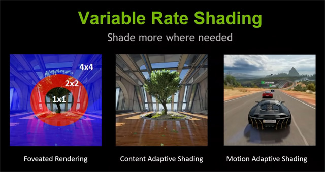
- In combination with eye tracking, where the eye focus has the highest resolution
- As defined by the game developer whereby the developer defines the resolution priority using an encoded texture.
- By detecting and rendering motion at a lower resolution
The graphics engine splits the screen display into a grid of tiles (arbitrarily 16×16 pixels) and applies a scaled pixel resolution depending on the priority seen within each tile, as defined by the developer or by eye tracking.

Here is an example using a 4×4 pixel tile, showing the savings relative to the highest quality:
- 16 individual 1×1 pixels (100%)
- 8 each 2×1 or 1×2 scaled pixels (50%)
- 4 each of 2×2 scaled pixels (25%)
- 2 each of 4×2 or 2×4 scaled pixels (12.5%)
- 1 single 4×4 scaled pixel (6.25%)
Note 1: any quality range from supersampling to course mapping to be rendered.
Note 2: the size of the tiles and the extent of scaled pixel sizes is ultimately arbitrary
Variable Rate Compute Shaders (VRCS)
A compute shader allows for a flexible mapping between compute threads and output pixels, which is a more implementation dependent explanation of the VRS technique.
Vulcan
Vulkan is a graphics and compute API that supports multiple platforms. It facilitates pre-emptive loading of assets on multiple threads in order to keep rendering frame rate consistent. Shaders can be compiled and cached when a program is initialised for the first time. Programming for Vulcan requires more effort and planning than OpenGL for which it is the successor.
Mesh Shaders
A mesh shader is preceded by a task shader and is followed by a rasteriser. The task shader divides a mesh into work groups. The work groups are passed to the mesh shader for parallel processing. The mesh shaders simplify the work groups into reusable arrays of vertices and attributes called meshlets suitable for efficient drawing by the hardware rasteriser.
Sampler Feedback
Sampler feedback is provided in Direct X 12. At runtime, sampler feedback provides information about what mip level is being used to render a scene and what part of a texture is being sampled. This knowledge can be significantly helpful to minimise memory use and thereby increase efficiency.
Ray Tracing
Ray Tracing is the collective/generic name for a method of rendering a scene as an image on a graphics device. In its simplest form, a mathematical ray is calculated from the players view point through each pixel in the image. When the ray reaches an objects surface the properties of the surface are taken into account with respect to the light sources that in the scene. A finite series of reflected rays are calculated sequentially until the final illumination level and colour are known. The result is painted into the image pixel representing the ray and the next pixel is then calculated until all the image pixels are complete.
Path tracing is a refinement of ray tracing whereby several rays are traced through different parts of the same pixel and the offset is selected randomly. This makes the final image much more natural and has a similar effect as anti-aliasing.
LOD
Large and complex models are stored with several increasingly smaller copies that have less detail in them. The smallest model is loaded when it appears at the furthest distance from players point of view. Larger models are loaded as the view distance decreases.
Upscaling
Upscaling means enlarging the frames of a game in real-time whilst enhancing or synthesising details such that the finished result looks native to target resolution.
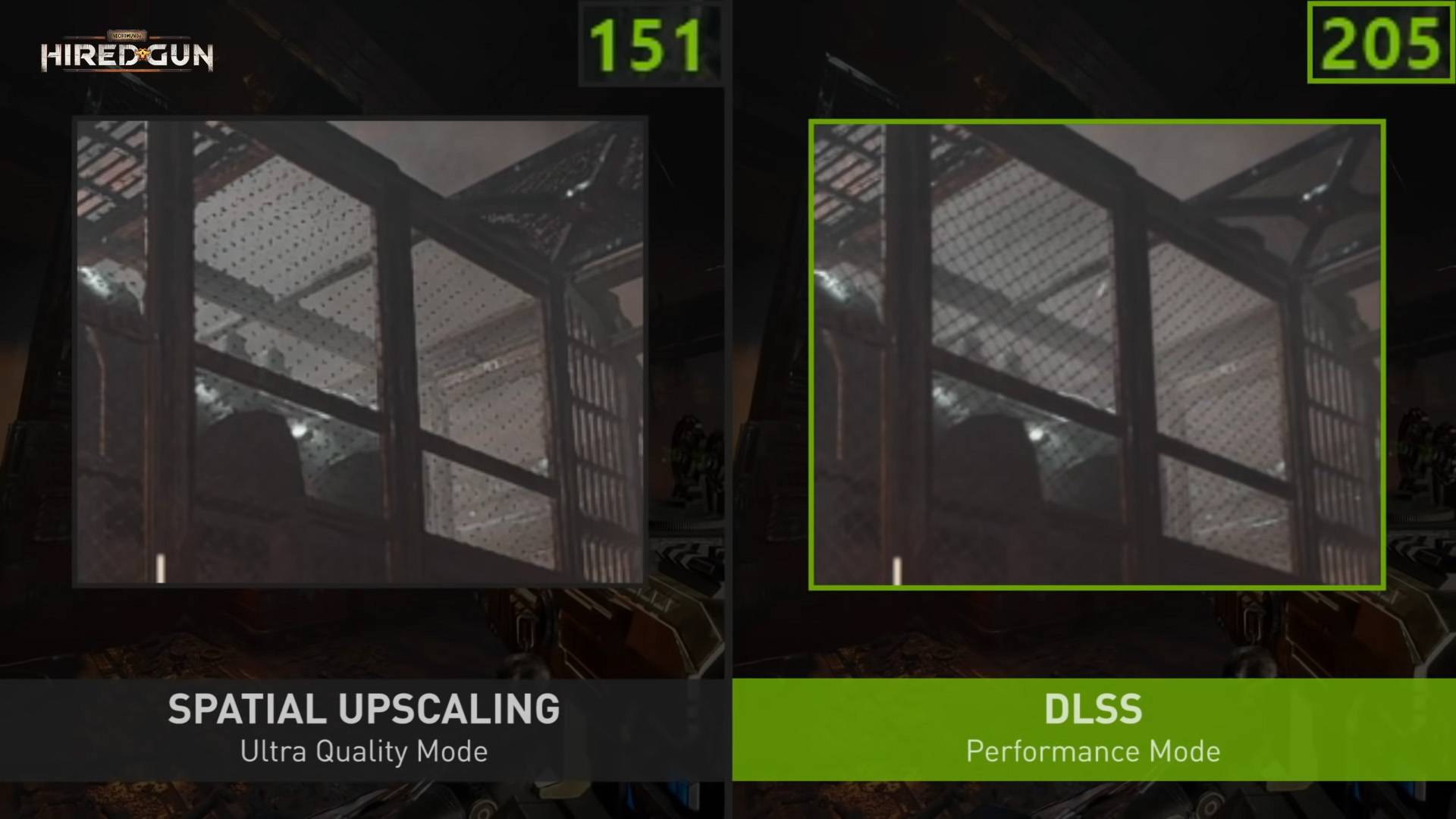
Spatial vs Temporal
Spatial upscaling means upscaling a frame using only the information within the frame. Temporal upscaling means upscaling a frame using data from the previous as well as the current frame.
AMD FSR & FSR 2.0
FSR is a form of spatial upscaling. It isn’t quite as effective as temporal upscaling but its close and easier to implement. FSR 2.0 extends the tech into temporal upscaling.
NVIDIA DLSS
DLSS stands for deep learning super sampling and is a form of temporal upscaling. It has been developed by Nvidia fir the RTX range of graphics cards. In order for a game or sim to use it, it must be programmed in at source code level.
Nanite & Lumen
Nanite is the name of the virtual geometry engine in Unreal Engine created for Unreal by Epic Games, led by Brian Karis.
Nanite Geometry
- Nanite is a complex graphics engine whose frame rate depends upon the display size rather than scene complexity. The basic unit is the triangle mesh. Nanite is a triangle rendering pipeline.
- Source geometry meshes from industry standard modelling tools are parsed into a new format when they are loaded.
- All of the reformatted data is stored in video memory across frames and is sparsely updated with changes.
- All Nanite mesh data is stored in single large resources that is accessible at any time.
- Triangles are grouped into clusters, clusters are rebuilt internally to simplify. the edges remain unchanged to prevent visible gaps between clusters.
- Clusters are culled using a hierarchical depth buffer, remaining clusters are matched with the lowest MIP level.
- Good occlusion culling is achieved by isolating the differences between the depth buffers of the current and previous frames. Anything new will be added to the frame.
- The visibility pass uses shaders to combine the depth buffer with (interpolated) textures and the result is stored into a GBuffer. The CPU cost is independent of the scene or the objects in view.
How Mesh LOD is Managed Over Time
- Clusters are arranged into trees of LOD levels dynamically, with unused nodes removed from the tree as necessary over time. The parent LOD has the least amount of detail.
- To prevent visible cracks forming in a mesh due to varying LOD levels across an object, groups of clusters are created and all members of the same group are given the same LOD level.
- As the LOD levels change:
- New groups of clusters are selected with the least number of (locked) boundary edges. This maximises the opportunity for internal simplification.
- For each group, individual triangles are merged and simplified by 50% using a Quadratic Error Metric to optimise the position of a new vertex in space with minimal error. This is not perfect but does work well. The level of error is stored in the group.
- The simplified list is reassembled into new clusters within the group.
- The boundaries do not change and cracks are eliminated.
- Additional information is added for close but unconnected clusters to control which groups the cluster end up in.
- The net result are two list of groups with the least number of locked edges, one with a LOD level one half of the other. When the level of error between the two is less than 1 pixel, the change between the LOD representations is imperceptible (via TAA antialiasing).
- A thread pool is used for culling LOD, supported by shader programming to ensure the mechanism completes correctly in all hardware environments.
- Occlusion culling is performed on the new frame and combined with the differences from the previous frame in order to isolate changes that need to be updated and given materials.
Rasterisation
- A software rasteriser is faster when working with small triangles (less than 32 pixels long).
- A hardware rasteriser is faster for large areas.
- The most appropriate rasteriser is used throughout the image.
Inefficiencies
- Currently Nanite does not work well with large numbers of gaps and holes, for example in subjects such as grass and tree leaves.
- Tiny instances cannot be culled easily.
- Visibility Buffer Imposters are objects that carry enough information to be rendered instead of small instances, but the lower resolution can be noticeable in specific circumstances.
- Materials are applied in tiles using information stored as a depth buffer. This code is being reworked.
Glossary
BVH – Bounding Volume Hierarchy. Any mesh object can be simply represented with a cube that completely encloses its extremities. Smaller mesh component objects a complex object can be represented in cubes of their own, grouped and enclosed by larger cubes nested inside each other.
Compute Unit – is (approximately) a group of GPU cores that share their own rendering units and cache. A GPU will have multiple compute units.
DAG – Directed Acyclic Graph. A hierarchical list of nodes where the relationship is flowing in one direction (eg: from parent to child or parent to grandchild, never from child to parent etc.). A child may have more than one parent.
HZB – Hierarchical depth buffer
Interpolation – Creating new values between two known values in even steps.
LOD – Level of Detail – related to the amount of detail stored in a version of a 3D model. Distant objects do no require as much detail as nearby objects. Related to Mipmap.
LZ – Lempel-Ziv compression replaces repeating blocks of byte aligned data with a short reference code. It is a straight-forward, simple, lossless compression technique used to reduce stored data sizes.
Mesh – a three dimensional net composed of a collection of evenly distributed points that are interpreted as vertices, edges, and faces according to context. A mesh can be moulded into any shape and is normally made visible by painting the surfaces with images or colours.
MIP – An acronym for a Latin phrase: Multum in Parvo, meaning “much in little”. Usually used as Mipmap or MIP level.
Mipmaps – a size-ordered list of progressively lower resolution images. Each rectangular image is half the size of the one before. Related to LOD.
ROP – Raster Operations
SRV – Shader Resource View
Shader – A small program used to render pixels, usually as a fragment of a larger image. There are specific shaders to produce specific outputs, for example ray-traced or vertex shading. Each type of shader will require its own specific type of source data to work with.
UAV – Unordered Access View