How Contactless Debit Cards Work
Contactless smart cards are miniature computers with no onboard power that communicate using a private encrypted protocol. It’s all rather ingenious.
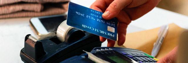
This article illuminates the process that occurs between a smart debit/credit card and a card reader used in shops. Although contactless cards are unpowered, they contain a micro-controller, memory and an inductive coil and this is all you need to complete a transaction.
Page Contents
The Antenna
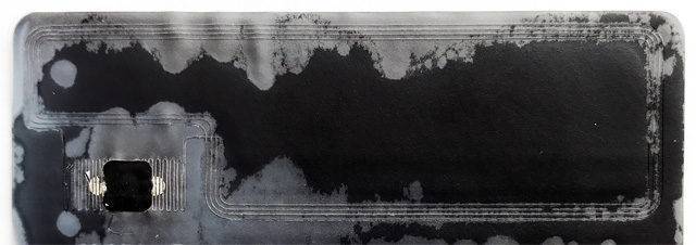
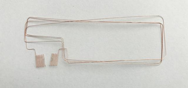
A contactless card has an antenna in the form of looped coils of wire that pick up electromagnetic energy by induction. Usually an antenna is used as an RF resonator, but not in this case.
The ISO standard requires a carrier frequency of 13.56 MHz to work at a distance of up to 10 cm between card and reader.
The range of the card and reader interaction is influenced by the number of coils in the card and fewer coils reduces the effective range. This is a good thing from the point of view of criminal intent and small sheet of baking foil makes a very effective shield (refer to video).
The antenna has three functions:
- To collect RF energy
- To receive transmissions from the card reader
- To transmit responses back to the card reader
The communication is half-duplex, meaning that only one side can talk at a time, and the protocol has to ensure that this process works smoothly.
The Power Source
The AC voltage from the RF field picked up by the antenna is rectified to provide a continuous DC voltage source. The antenna and rectifier combination provide a steady power source as long as the card is within the reader’s electromagnetic field. When the card voltage reaches a threshold value, the device will switch on and begin to operate.


The Micro Controller
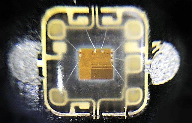
The visible surface of the micro controller’s container is a metal pad etched into 6 electrically isolated segments. Depending on the chip design, the underside of the top segment may contain external memory for the micro controller to use. The micro controller itself is contained within the boundary of the central segment.

The pads surrounding the chip in the centre are used when a card is inserted directly into a card reader. They provide physical electrical contact with the payment machine when a contactless exchange is not possible.
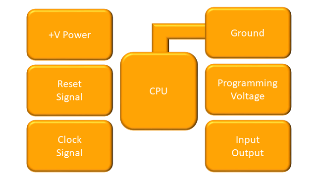
The microcontroller is programmed with encryption and decryption capability together with instructions to manage a card reader’s communication protocol. Its memory carries its identity and numeric keys that will validate the card for use.
During each use, a special code is generated dynamically by the card and this will be validated by the card issuer remotely. The dynamic code combats criminal card cloning.
The Communication Technique
The reader and card are using amplitude modulation to communicate. In this example the carrier wave is 13.56 MHz, the modulation (sub-carrier) frequency is 847.5 kHz and there are 16 carrier wave oscillations per modulation cycle.
The data bits are encoded using Modified Frequency Modulation to reduce bulk and increase resilience.
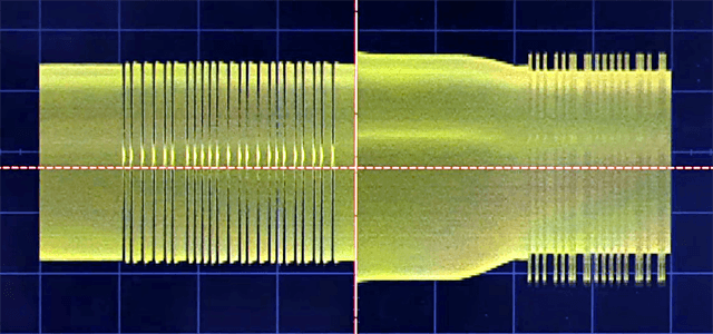
The oscilloscope trace shows a data exchange between a card and reader. The left-hand side of the frame shows a communication initiation request from the reader followed by a response from the card on the right.
The Contactless Sequence
Once the communication protocol is established, private encryption keys are exchanged and the transaction confirmation can take place. This is the full sequence of events:
- A contactless smart card is brought near a card reader
- An antenna wrapped inside the circumference of the card picks up energy from the radio frequency (RF) field provided by the reader.
- Energy continues to be absorbed by the card while it is within the RF field.
- The absorbed energy powers the micro-controller in the card and switches it on.
- The card reader establishes a connection with the card and a clock signal is used to guide the exchange of data between the reader and the microcontroller.
- The card reader sends the card an encryption key.
- The card decrypts the key and uses the result to encode its ensuing communication with the reader.
- The reader sends the transaction details to the card.
- The card encodes a document containing the payment details signed with its private key.
- The card sends the document to the reader.
- The reader sends a receipt to the card
Newer cards can now operate on low voltages (1.8v) which should make them more reliable.
A Card Being Analysed
Here is Dave Jones of EEVBlog being very enthusiastic. The video is to do with investigating the security of a contactless card. If you stick with it, you will see Dave isolating the communication protocol on an oscilloscope. He does stress that the communication is carried via amplitude-modulated magnetic fields via the transformer style inductance coupling.
References
- www.rfid-handbook.de
- www.eevblog.com
- securetechalliance.org
- cardswitcher.co.uk
- analogictips.com
- wiki.analog.com
- magazines007.com
- os.mbed.com
Disclaimer
Care has been taken to keep the information in this article as accurate as possible but errors are possible, so be aware of the full disclaimer here.
